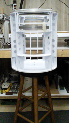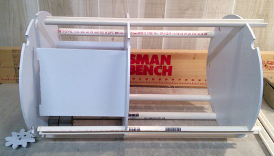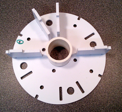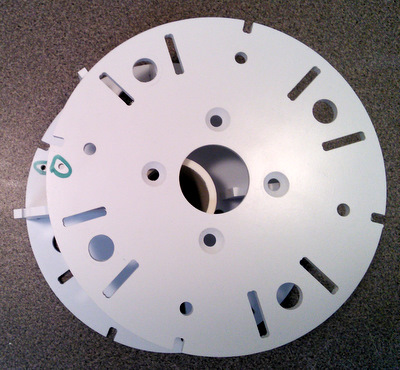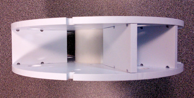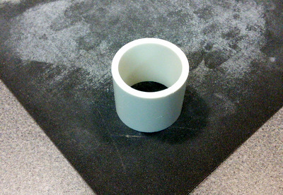
The CS:R NextGen Frame
Dry Fit & Assembly
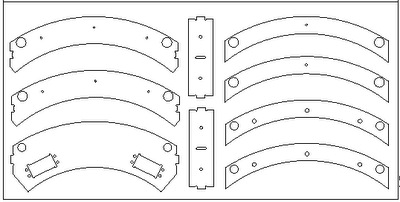
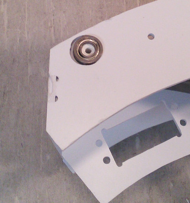
Revisions![]() Ring4, Core4, Utility Arm Ring (upper). Ring4 now has mounting holes for the Rockler bearing while the Core4 plate has holes for a dome motor and slip ring mount. |
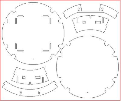
![]() Core2 & Core3, Under Shoulder Rings, Door Ring (top), and Door Ring (middle) 05/16/20 - The PVC Core 2,3,4 panels have been replaced by the Tab Core panels. The instructions that follow have not been updated. (follow the link!) |
It turns out that Ring4 is symmetrical and
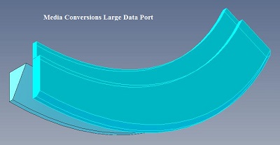
can be installed upside down. ![]() This is the MC variant of the Large Data Port. The lip on the upper part mates with the notch on Ring4. |
here's a better view of the notch in ring4 shown above. this feature should be facing down (into the body of the droid) NOTE!! - you should hold off on installing your LDP until after you have mounted your skins to the frame. Otherwise the skin mount gets more complicated. |
Left: top view of LDP installed on Ring4 Above: bottom view of LDP |
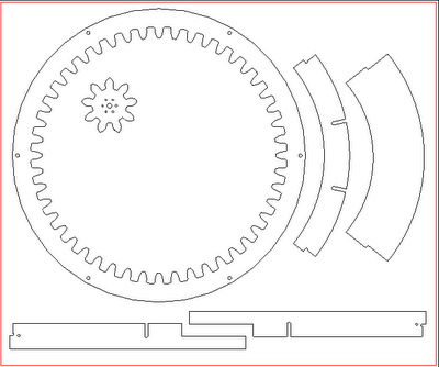
|
![]() Dome Motivator, door ring middle, rear door ring, inner door ribs |
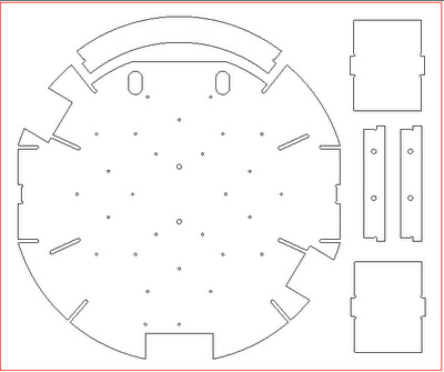
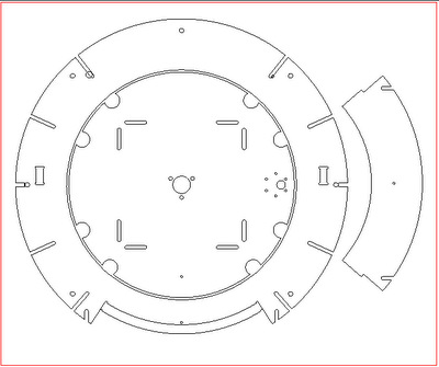
![]() Ring1 Frame Bottom (the extra holes are for gluing to Ring0), Top Door Ring, Ankle Slice Panels, Utility Arm Box Ribs |
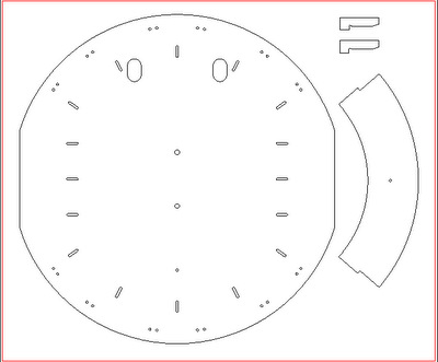
![]() Ring0 (also serves as the skirt bottom), Utility arm ring (lower). Rib slots end with Ring1 so it's not necessary to fill in the joints. The two small parts are the rear door keys. See rear door frame assembly for more information. [02/10/16] Do not Glue Ring0 in place until after you mount the skins. Having it removable will make the skin mounting easier! |
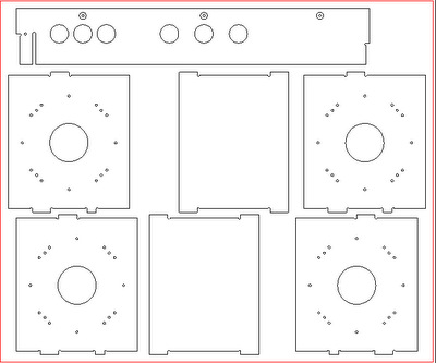
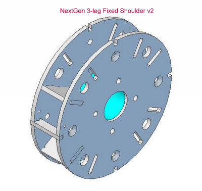
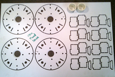
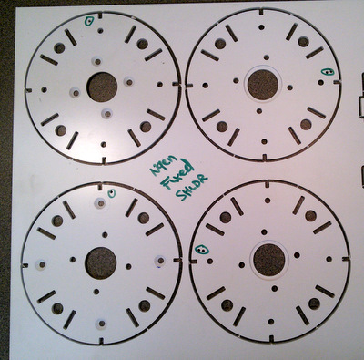
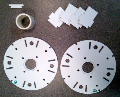
![]() Plates - shoulder (4), core mounting plates (1), and a rear door rib. The shoulder plates now have mounting holes for both 2-leg and 3-leg configurations. |
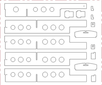
A Note about the Shoulder Plates shown above. The mounting holes are smaller, 1/8 inch, than what you will see in the assembly pictures. It was done to accommodate CS:R leg specifications that call for 1/2 inch bolts. But those were derived from designs done by builders of aluminum droids. Meanwhile there are lots of builders who used Dave Everett's Styrene Droid Plans. Dave used an entirely different bolt pattern. I chose to leave the decision up to the builder when I reduced the hole sizes. To follow the assembly instructions shown here you can drill out the holes at top/bottom/left/right to 1/4 inch and use 1/4-20 bolts to hold the plates together during dry fit and glue up. Leave drilling the remaining holes to when you are ready to mount legs.For more of the details on mounting legs, jump ahead to the section on Fixed Shoulder Hub assembly. | |
![]() Ribs1 - ankle slice rings and skin attachment points |
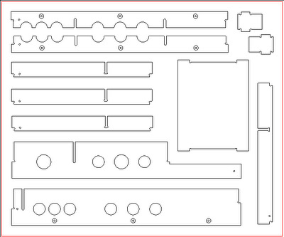
![]() Ribs2 - and the second Core mounting plate. |
Above: these are the skin attachment points. shown above in the Ribs1 panel they are not discussed here in the frame assembly. Right: they are installed in the droid's "armpit" and are used to anchor the end joints of the 1/2 wrap engraved skins. you'll find more information on the web pages that talk about mounting the engraved skins. |
|
Here is how the skin attachment points work. Only one problem. They don't leave enough clearance around the Fixed Shoulder. [The large holes in the shoulder just happen to fit over the 1/4-20 bolts] |
If you have already glued the attachment points in place you can use a dremel tool to grind off enough to give you clearance around the Fixed shoulders. Remember they get wrapped with a layer of .040, so you'll need that much on both top and bottom. |
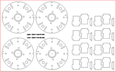
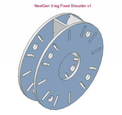
![]() CS:R Shoulder Hub |
![]() NextGen Frame Utility Arm Box (.125 thick) |
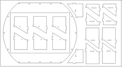
![]() NextGen Frame Skirt Parts (.125 thick) |
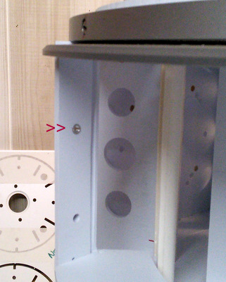
Ring1 (frame bottom) is cut to allow mounting of the Octagon Port. While the cut in the front lines up, the one in the rear does not! |
I made the Assumption that the Rear Octagon Port was located in the same position as the front one, and simply reflected the cut from one side to the other. I should have checked. |
To fix this problem, use your favorite cutting tool and follow the guide lines in the picture above. If you have already glued the Ring0 (skirt bottom) to Ring1 then use a Dremel with a sanding drum to reduce the thickness in the area shown. |
|
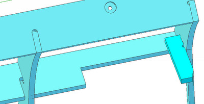
Above: This is the space behind the Pocket Vents. The rib shown was notched for clearance. Just not enough. Right: there are 4 ribs on the Ribs-1 panel, only 2 need to be notched but it was easier to notch all 4 on the panel. |
|
Both
ribs that need to be notched are on the Left hand side of the droid
when viewed from either the Front, (Shown Above Left) or from the Rear
(Shown Above Right) Left: Again, use your favorite cutting tool to extend the notch upwards as shown. |
![]() Malcolm M sent me photos of the middle door rib slots not lining up with the outer rib slots. |
![]() when I went back to the CAD design drawings I found my mistake. |
you can just barely notice the difference in the rib position if you compare the middle of the rib to either end, |
Now, I had assembled two rear doors and never noticed the problem. When I went and took a closer look at the rear door with skins on it I noticed that the center ring is bowed just a little. In practice, it's not enough to cause a problem. The CAD drawings have been fixed and all currently shipping frames have ribs with the slots in the correct places. |
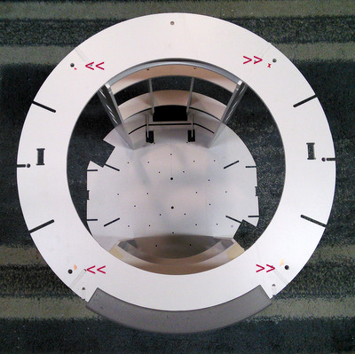
Ring 1 with FOD (front of Droid) and left of Droid markers |
Ring 4 the LDP cutout serves as front of Droid marker |
![]() Ring 0 (this face has the slots for the skirt parts) the two oval cutouts are finger holes used to pop the rear panel open. If you are not going to have a skirt simply turn the ring over and glue this face to ring 1. |
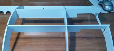
From left to right: Utility Arm Ring Upper & Lower, Utility Arm Box Ribs (2), Rear Door Ring (note no FOD hole), Rear Door Ribs(2), Shoulder Ribs(4), Ankle Slice Ribs(4). Note that the Utility Arm Box Ribs shown here have changed. See Below. |
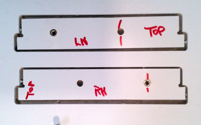
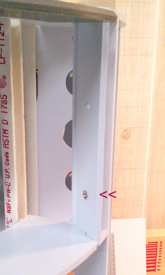
![]() |
Left: In order to have a way to anchor the
Utility Arm Box to the frame I've added holes and Thread-Serts (also
called NutSerts) to the ribs.
There will only be one on each side to correspond to the tip of the
utility arm. To get to the screw you'll need to extend the arms and
then reach
in with a screwdriver to remove the screw. I'd use an Allen head since
it will stay on the end of the driver when you go to insert the screw
initially. The NutSerts fit into a 1/4 inch hole and take an 8/32 screw. Do Not Over Tighten the screw. I got mine from AllensFasteners.com they are THREAD-SERT (ALUMINUM) Standard Thread Size: 8/32 YOU DO NOT HAVE TO BUY THESE> I Install them for you! |
Thread-Serts/NutSerts are normally used where Blind Fasteners are required. Typically where you can't get to the back of the hole to hold a nut in position. To insert a Blind Fastener you usually need a special tool that pulls the fastener together expanding the barrel and locking it in place. However, that's not needed here! I simply insert the fastener in the plastic part and then compress it in a vise! | |
Under Shoulder Ring(2), Shoulder Plate(4) Ankle Slice Ring(2), Ankle Slice Plate(2) |
Rear Door Parts: Bottom Ring, Top Ring, Middle Ring(2), Inner Rib(2), Outer Rib(2) |
parts sometimes have a raised edge where the part was cut from the panel. there are two ways to remove it. sometimes I use the edge of a utility knife |
and other times I use a file. |
The rear door uses magnets to hold it in place. I get mine from K&J Magnetics. There are pockets in the mating door halves. The trick is to get the magnet polarities correctly when you are all done. |
Take a moment to review the handling instructions on K&J's website. http://www.kjmagnetics.com/safety.asp It's easy to chip a magnet. Buy extra magnets as more than one flew off my workbench, attracted by a nearby piece of iron. If you drop one on the floor it may be difficult to locate! |
the easiest way to separate a magnet from the stack is with a wiping/sliding motion. Make sure the pocket is clean and the magnet seats fully. If there's a problem pulling up on the stack will pop the magnet out. There's also a hole if you need to push from the other side. |
Note:
while you will see me installing 3 magnets in the door pockets I've
determined that 3 is overkill and only 2 are needed. One at top, one at
bottom. Here's the 'trick' to making sure the magnets mate properly. stack a second magnet on top of the ones you just put in! They will mate by default. |
Note:
I had already put my rear door frame together before I realized it
would be simpler to put the magnets in first. Do these steps before you
assemble the door frame. Now, press the mating door frame rib against the rear frame rib making sure the magnets seat into the pockets. separate the two pieces by sliding them apart otherwise the magnets will just come out again. |
|
Once you've got mating magnets in both pieces you will have to be careful handling the parts around metal objects. Before a magnet files out of it's pocket put a drop of Cyanoacrylate adhesive (super glue) around the edge to hold them in place. |
Above: Shoulder plates come in pairs. For now I'm using a 1/4-20 bolt to hold them together Right: The plates fit into the Under Shoulder Rings |
|
Assemble both sets |
Then insert them into Ring4 |
Locate the 4 Shoulder Ribs. Install one on either side of the Under Shoulder Ring. |
|
Since it's an end slot, put some tape on the rib to ring joint to hold the parts in place while you are doing the rest of the assembly. |
Turn the assembly over. Making sure of the front of Droid orientation, insert the Shoulder Ribs into Ring1. |
At the front, install the two Utility Arm Ribs. Use tape to hold them in place at the top. |
Install the Upper (with slots) & Lower Utility Arm Rings. |
![]() Install the two Utility Arm Box Ribs. |
![]() Note: there are now left/right versions with NutSerts installed. |
Turn the frame around to the rear and put the two Rear Door Ribs in place. Note: there are now left/right versions. The Ribs have pockets for magnets that must face the door frame. |
Add some tape to the bottom to hold the rim in place securely. Note: the bottom slot has been made deeper to hold the rib. |
Above: Insert the rear door ring. Right: Turn the frame to one of the shoulders |
|
Left: Insert the Ankle Slice Ribs using the top of Droid holes for orientation. Insert the Ankle Slice Plate into the Ankle Slice Ring. |
|
|
Left: Insert the Plate/Ring assembly into the Ankle Slice Ribs. |
Above: The Weldon #xx glue dries evaporates really quickly. Have your clamps and alignment bolts ready to go before you apply any glue. Right: use 1/4 inch bolts to hold the plates in alignment. |
|
The shoulder plates you get will not be drilled with full size holes. For hole alignment, to glue the plates together, you can drill the 4 holes that I have used for 1/4 inch bolts (top, bottom, left, right) while assembling the shoulder plates above. The remaining holes (see the parts.pdf drawing) are for: the legacy 3-leg fixed shoulders (the ones at 45 degrees - drill to 1/4 inch) or CS:R style legs (the ones at +/- 36 degrees - drill out to 1/2 inch). For the CS:R legs Do NOT drill out BOTH holes. You only need to drill one set in each shoulder! Drilling both holes could weaken the shoulder plate as they are close together. You might want to wait till the frame is assembled to make sure you drill the correct set of holes! | |
Left: have your clamps pre-set for the thickness of the plates. |
Above: I'm using a BIG applicator to make it easy to get a lot of glue applied quickly. |
Yes, even though the slot is off center it is possible to put the shoulder plates in backwards. Make sure they fit between the rib slots! |
|
Above: Once the glue dries you can turn the assembly over and add the Under Shoulder Rings (partial) and then glue them in place. Right: turn the frame upside down again and now install the 4 shoulder ribs. Use the Under Shoulder Rings for alignment. |
|
turn your frame so it's right side up with the front facing you. |
install the utility arm ribs (note top of Droid holes in the ribs) they are trimmed on top to enable the utility arm box to slide out. |
Turn the frame around so you are working on the back and install the rear door ribs. the magnets should be facing you. [ sorry, there are no magnets in this pix] |
tape the bottom edges of the rear door frame to hold them in place. |
when you the Weldon #3 on joints that are in the surface of the frame that's in contact with your workbench you should expect some leakage. make sure that the surface won't be harmed by the cement! [don't do this on your dining room table!] |
Left: the Sliders on the bed of the 3D printer. Above: sample Sliders |
|
This is how the sliders fit in the Core PVC pipe. The fit will be loose. That's OK since you need some clearance in order to be able to slide the Core in. |
The slot in the slider needs to be a tight fit on the ribs in order to glue it in place. The inside corners of the channel are slightly rounded. Use a file to sharpen the corners of the slot. |
Sliders are
installed in a descending spiral pattern. This is done so that you need
to engage only one slider at a time when you insert the Core. Note the
red marker on the top of the rib for slider #1. There is a similar red
marker on the Core pipe for that position. Each of the first 6 sliders in the sequence shown to the right is 1/4 inch lower. Slider #7 starts a new sequence (the front two ribs are shorter to allow clearance for the utility arm box) |
|
The sliders are staggered in height, getting lower by 1/4 inch as you proceed around the top ring (first 6 sliders). | |
Above: Simply line up the two red markers and drop the Core into place. Right: this Core was assembled with the dome motor on the Droid's Left side (your right in the picture). Turn the top Core plate over if you want it on the Droid's Right. |
|
The next 4 pictures show the locations of the sliders with the core in place. If the Core binds when you go to insert it simply identify the core that's too tight and sand down the surface slightly until it's easier to insert. | |
Use tape to make sure the ribs are in close contact with the bottom shoulder rib |
tape both front and back then glue the joints. |
Left: insert the ankle ribs in the frame. Note the orientation of the ankle slice rib slots. Above: It's your choice. you can assemble the ankle slice plates to the ankle slice rings and then insert the assembly into the frame, or you can insert the ankle slice rings into the frame and then put the ankle slice plates into position |
|
Left: make sure the ankle slice plate is in good contact with the ankle slice ribs and then glue it in position. |
Rings aligned |
all of the notches line up |
Rings deliberately mis-aligned |
While some notches line up, some do NOT. It's a small amount and the PVC pipe will bend to fit, but then bind when inserted into the frame. |
Don't try cutting the PVC pipe without something to protect your hands! This was my first attempt at a fixture for cutting the pipe. However, PVC is tough stuff and I didn't like the results I was getting. |
|
This was the fixture I eventually developed. I mounted a slitting saw on my CNC router and hand wrote G-code to cut the slots. |
|
If you've decided to cut
your own parts for the NextGen Frame let me know. I can supply the PVC Core Pipes and the mating Sliders at nominal cost. |
before you start the next step take a moment to check your ring alignment |
make sure you can see BOTH "front of Droid" markers |
Left & Above: put tape on the PVC pipe so that the cut edges stay slightly below the edges of the Core rings. |
|
run a bead of cement around the edge of the PVC pipes in the Core 3 ring to hold them in place |
transfer the tape to the Core 4 ring and then run a bead of cement on those joints as well. While you have the cement out you can also put a bead on the Core Panels where they join the Rings. |
Left: place the core upside down Above: make a set of marks on the pvc pipes 1 inch up from the bottom |
|
Above: mark all of the legs Right: wrap tape around the pipe ends at your marks. The tape will hold the lower core ring in place while it's glued. |
|
The reason we do this is to allow space under the core for the bolts that hold the center ankle in place. |
Take a moment before gluing to verify the "front of Droid" holes line up! |
then run a bead of glue around the joint. |
![]() |
![]() Left: That's the 30in stool the frame fell from. Above: The major damage was to the center core, where the glue joints to the pvc pipe failed. The frame joints were made using SciGrip #3 which is a solvent cement that fuses the two pieces into one. All of those frame joints, and the one's in the rear door were still intact. |
![]() |
![]() Left: the bearings in the utility arm box unseated themselves. I never put the screw in that would hold it in place. Above: Since the SciGrip cements I had available don't bond to the PVC pipe I'm going to try using Plumbers PVC Pipe cement. |
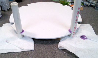
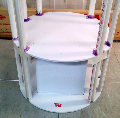
![]() Above: I tried it out on a spare piece of core using some shorter pieces of pipe. Be careful with the 'purple primer' it will stain just about anything it comes into contact with. Right: as in the earlier assembly, the core is upside down. The flat surface insures the top edges will all be even. The tape keeps the pipe segments from rotating while glue is applied. Note the glass plates. They are to keep the work bench clean. |
![]() |
![]() Working space is tight. Only glue two pieces at a time. I applied the primer and cement using Q-tips. Gently roll the Q-tip so the primer is squeezed out and runs down into the joint. I did 1/2 a pipe at a time then got more primer on the Q-tip for the second 1/2. Do two halves of one application, then do the second pipe. I applied primer twice to each pipe (it evaporates quickly) then followed up immediately with the clear cement. Then move onto the next pair of pipes. When all 8 are glued let the glue harden overnight before going onto the next set of joints. |
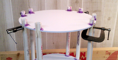
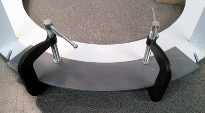
![]() When I glued the bottom core plate on originally I used tape to create an edge for the core plate to rest against while the glue was setting. This time I used C-Clamps since I didn't think the tape would stand up to the primer and it would be difficult to clean up if the plate slipped while the glue was setting. |
Arm Box Assembly | |
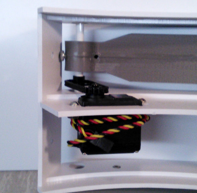
Left: The Arm Box consists of 2 side pieces, a center piece where the servo mounts are (with tabs), 2 top/bottom pieces (with notches), and 2 sets of bearing mounts rings (one set with 3 holes, one set with just one hole in the middle). Above: Start by putting the sides into one of the top/bottom pieces and (below left) taping it in place |
|
with the tape holding the bottom in place insert the center servo mount. again tape the edges to hold it in place. |
|
Tape the remaining top/bottom piece in place. Glue the arm box joints. |
|
Above: The bearing mount plates with the three holes mount to the top & bottom rings of the arm box (note the matching 3 holes in the arm box top & bottom) Right: file off any excess glue that might be on the inside edges of the joint. It will prevent the bearing rings from bonding to the top/bottom rings. |
|
Above: top (& bottom bearing ring in position) Right: I used spring clips to clamp the pieces together for gluing |
|
bearing ring glued in position |
the FR188-ZZ bearings fit snugly into the bearing rings. |
Utility Arm Assembly & Mounting the LDP (lower part) | |
The utility arms have 3 pins, made from 3mm filament, to hold them in alignment while they are being glued together. If you are going to put a LED at the arm tip extend the channel threw the tip. |
The arms that I ship to customers are already drilled for the filament. |
cut the pieces short as there's not much depth in the arm halves. |
make sure all 3 pins line up and that the edges are together before you clamp them |
Above: clamp the halves together, insert a 1/4 in shaft (or a bolt) to act as a fourth alignment point Right: there's a hole for an anchor screw to hold the Utility arm in place but still permit some up/down adjustment note! for better access move the hole |
|
Cut a piece of Plastruct 1/4 in tubing to length I've shown a tubing cutter here, the last time I tried mine it was too dull to cut the plastic. You can use a sharp knife! |
Center the Utility arm and tighten the screw to hold in position. DO NOT Over Tighten the screw. |
The CS:R Large Data Port pieces have no visible means of Support. The three holes in the top/bottom arm box rings are for 4/40 screws that fit into tapped holes in the LDP bottom part. |
|
Above: To make it easier to remove the screws I used allen head screws (and only 2 of them) Right: arm box in the NextGen Frame with LDP upper part in position. My version of the LDP has an extension on the rear edge that fits into the pocket in the underside of the top ring. |
|
Utility Arm Motivators | |
My original design for the arm motivator called for the use of GT3 timing belt loops. I was going to 3D print utility arms with the GT3 sprocket attached and print a separate sprocket to be attached to one of the servo 'horns' supplied with the servo. It was going to be difficult to attach the sprocket to the horn and then there was still the problem of tensioning the timing belt. I was searching for sprockets, for a different application, when I came across sprockets that could be mounted directly onto a servo from Servo City. They make a line of .1277 in plain bore sprockets, servo sprockets and plastic chain. While SDP-SI also carries .1277 sprockets and chain, they do not have servo mount sprockets. I used an 18 tooth servo socket and a 20 tooth plain bore sprocket on the utility arm shaft (it's a TIGHT fit). It takes less than 6 in of chain to form the loop (it's sold in 1 ft increments). | |
![]() |
![]() |
While this approach looks good, there is one fatal flaw that I overlooked. The plastic chain is a 'snap-together' design, but it's only rated for a 4lb tension. Just about any obstacle is sufficient to cause the chain to pop open. given the design of the arm box, it's not possible to re-string the chain without removing the arm box from the droid. | |
[7/22/18] The Utility arm motivator project was dormant until I encountered a new product development. Servo City began offering MXL sprockets designed to attach directly to R/C servos. [They offer both Futaba and HiTec versions!]. While I was attempting to 3D print mating sprockets to attach to the Utility Arms my good friend PaulG (aka The Hobby Guy) came up with a more elegant solution! Simply drill out the R/C sprocket with a .25 drill! All that remained to do was to come up with a way to provide tension for the belt drive. What follows is the design that I've worked out, |
Utility Arm Motivators V3.1 | |
below: The Arm
Box panel itself is mostly unchanged Right: the changes were made to the servo mounting cutout and the bolt holes used to hold the servo in place. |
|
Servos above: The general assumption is that servos, under normal conditions, are more or less indestructible. When you work on your Arm Boxes, make sure you are over a work surface, this is what can happen when you drop one on the floor! right: if this happens to you, you can get (from Hitec, in any case) replacement case parts to make repairs! |
|
for those of you who read Mad Magazine (I haven't in a long time!) this step is usually the one that's accompanied by the Sproing! sound and parts flying all over the place! - fortunately that didn't happen! |
|
To complete the repair, transfer the ball bearing to the replacement case lid and reverse the dis-assembly process. |
Because we are going to mount using the top of the mounting ears you have to file off the piece of molded in case reinforcement. |
Above, Left
& Right: There's a lot of symmetry in the Arm Box parts. It's convenient to label the center piece where the servos mount with top/bottom designations and also note where the sprocket (top of servo) and body (bottom of servo) will be mounted. Right: take a moment to remove any rough edges in the servo mounting slots. You will only be using one slot, the one closest to the ball bearing, |
|
Mounting the Servo Hardware |
Left: for the
next steps of the assembly
a small bench vise will be helpful. You are going to be installing
nylon lock nuts. You will find a 5/16 open end wrench helpful and an
appropriate screwdriver. And a third hand if you don't have a vise! NOTE: although Phillips head screws are shown here that's only because I have an assortment of them. Socket screws would be easier to install since the driver won't slip off of the head. In addition to the Servos & Bearings, there are a number of small hardware parts that are needed for the assembly. I've made a list that you can download here: Parts List. |
Install a #6-32
x 5/8 screw where shown. It will be
the fixed anchor for the spring. |
For this screw you can tighten the nut all the way. |
Install a #6-32 x 5/8 screw in the single hole on the opposite end of the Servo. This will be the pivot for the Servo. Tighten all the way and then back off ~ 1/4 of a turn. The Servo should pivot freely. |
|
Above: For the final screw you need to modify a #6-32 nylon nut by drilling out the threads. We'll be using it as a low friction pad. Use a #28 drill (#6 clearance). You will need 2, one for each Servo. Right: hold the nut with a pair of pliers. If it 'grabs' on the drill bit it will hurt your fingers! |
|
Install a #6-32 x 3/4 screw, with the drilled out nylon nut under the head, in the mounting hole the farthest away from the fixed anchor (the first one you installed). Tighten all the way and then back off ~ 1/4 of a turn. The Servo should pivot freely. |
|
Install the
spring between the two screws. I would suggest a small pair of needle
nose pliers (jewelers pliers) for this step, Avoid unbending the loop
at the end of the spring. Do this step in a location where you'll be able to find the spring if it slips out of the pliers grasp and gets loose. You might want to consider buying extra springs to cover that eventuality. The Screw threads act as natural 'detentes' to hold the spring in place. Not shown: When you have completed mounting your servos, you can attach the MXL sprockets to them. |
|
Attaching Sprockets to Utility
Arms In order to use the MXL sprockets on the Utility Arms you need to drill out the servo mounting hole using a 1/4 in drill. Right: I preferred to do that using my drill press to make sure the hole is square to the sprocket. |
and pliers to keep my fingers attached to my hand! |
Slide the sprocket onto the tubing and like up one of the holes in the center of the utility arm. It should be a tight fit. |
using the sprocket as a guide, drill a hole into the utility arm using a #43 drill (tap drill for a #4 screw) |
I'm using a #4-40 x 3/4 screw to keep the sprocket from rotating. You can tap the hole to cut threads into the plastic. |
|
Installing Utility
Arms in the Arm Box |
First, remove the outer bearing. Second make sure the flange side of the inner bearing is facing the Utility Arm. Loop the drive belt over the servo sprocket, then rotate the arm so that the shaft enters the inner bearing by about 1/2 inch. |
align the outer end of the shaft with the center of the bearing hold and slide the shaft into the hole. |
Replace the bearing and you are almost done! Screw two #6-32 x 1/4 screws into the ends of the tube to hold it in place. |
![]() There is a pocket cut into the underside of the top ring. The upper half of my 3D printed LDP has a matching extension on the back. |
![]() While you can drill threw the LDP's extension and the top ring and tap the holes in the ring so you can bolt the LDP upper half How often do you think you'll need to remove the LDP and/or replace it? I'd just glued mine in place. |
NOTE!!
- you should hold off on installing your LDP until after you have
mounted your skins to the frame. Otherwise the skin mount gets more complicated. Believe Me. It's easier to remove the Rockler!!! |
|
I'd seen the Commando
Eight's Instructions on "preparing" a Rockler in several Forum
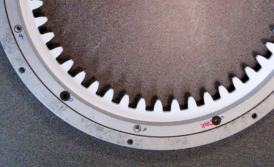
posting threads: anybdy-know-size-of-the-long-screws-that-poke-through-the-rockler-and-up-to-dome - post #3 possible-answer-to-rockler - post #5 As well as instructions for removing the Steel balls and replacing them with Acetal balls to make the bearing quieter. So review that material before proceeding. I also (will) have a web page for Rockler Bearing Prep. |
|
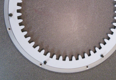
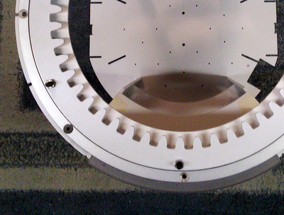
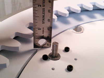
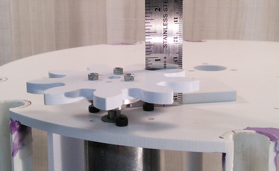
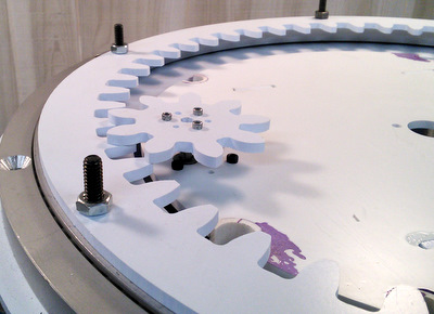
![]() With the Rockler prepared, bolt the Internal Gear of the Dome Motivator to the inner race. Extended length bolts give something for your Dome to mount to |
![]() With the internal gear installed you're ready to mount the Rockler to the Frame. |
![]() While there are 7 bolt holes for mounting the rockler, only 4 are reasonable to use. |
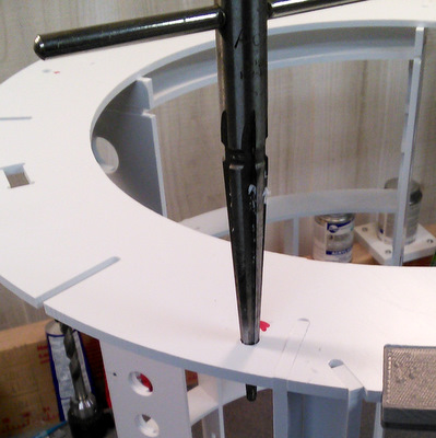
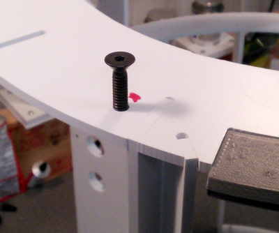
![]() Drill or Ream out the holes so that the 1/4 inch bolts are a smooth fit. |
![]() |
![]() Then bolt the rockler bearing to the frame |
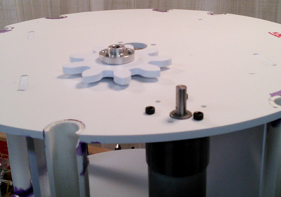
![]() Mount the Pololu Motor to the Core. Note Pololu's warning and use the correct length bolts. Mount the hub to the Spur Gear. |
![]() Insert the Core into your frame and verify the height of the top of the Internal Gear. Mine was about 3/4 inch. |
![]() With the Core removed from the frame, install the Spur Gear onto the motor shaft. Block it up while you tighten the setscrew so that it's on the flat of the motor shaft. |
![]() When you install the Core in the Frame make sure that the gear teeth line up properly. You can rotate the Rockler to do that. DON'T Just Drop the Core and hope for the best! |
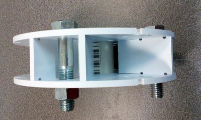
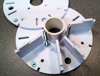
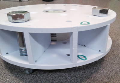
![]() Above: Parts in the panel plus the 2 pieces of PVC pipe. Right: The left hand pair of hub pieces have been turned over so you can see the countersunk holes. Note the single and double holes (circled) that denote which set the parts belong to. |
![]() |
![]() Above: not all of the ribs are shown. The smaller rib is a filler so the skin has something to glue to. Make sure the pocket for the pipe is on the inside. Right: typical parts placement. |
![]() |
![]() |
![]() Left: line up the two marker holes and fit the upper half of the hub in place. Above: A rib has been left out so you can get a better view. The Pipe should just fit the space available. |
![]() Left: If the pipe is oversize, you can reduce it's height by rubbing it against a piece of sandpaper on a flat surface. |
|
For CS:R Shoulder Hubs | |
![]() Above: check the fit using 1/2 in bolts. Right: Filler rib provides glue point for skins. |
![]() |
For Media Conversions (Dave Everett Styrene Droid) style shoulder hubs (read the note above again about bolt lengths!) | |
![]() |
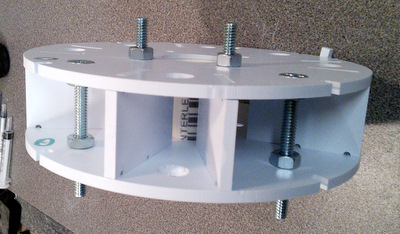
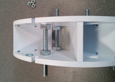
![]() Left: start out with the alternating bolt/nut pattern. Make sure the bolts going into the frame are long enough to go threw the 3/8 shoulder plate. Above: nuts on the outside serve to hold thing together. |
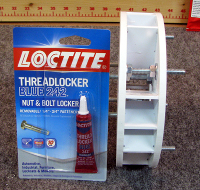
![]() Above: Once all of the hardware is in place you can add the filler rib Right: don't forget you'll want to use a thread locker to make sure the nuts don't work themselves free. |
![]() |
For instructions on Wrapping the shoulder skins see the instructions for my 3-Leg Fixed Shoulder |
Front View with Utility Arm Box in place. |
Utility Arm Box (only partially assembled) with a servo shown. |
Side (Shoulder) View |
Rear View with Rear Door in place. |
Rear View with Rear Door Removed. |
Home |