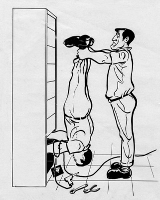
R2 is Not Designed for Accessibility
I wanted something better than the 'stand on your head' posture most of us have to take when working on R2's insides!
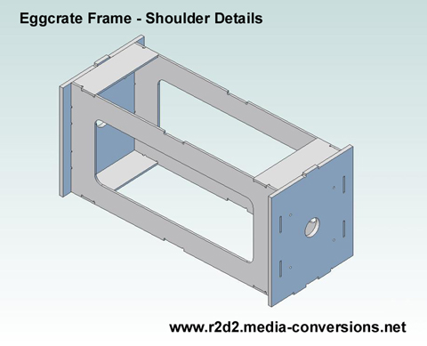 |
In the CS:L frame I built a box
beam
that links the
two shoulder plates
together for strength. The
cross brace pieces are set back from the edges because otherwise they
would interfere with the ribs. In order to add a removable rear panel to the existing design my original thought was to add a second box beam connecting the two ankle plates at the bottom of the frame. |
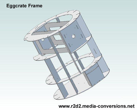 |
Adding
a second box beam at the ankle slice (the beam itself is not shown
here) would have only further interfered with the already limited
accessibility to the inside of the frame. Just the opposite of what I was trying to achieve! |
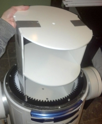 He removed the cross pieces of my Shoulder Box and added a cylindrical center core - here a taped up version is test fit. |
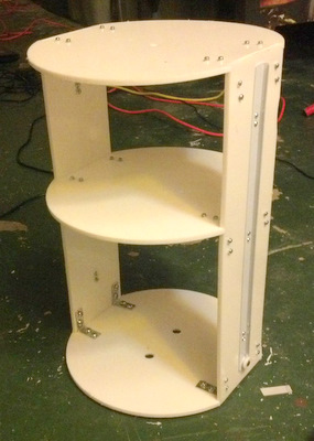 This finished version of the core has drawer slides attached to tie it into the frame |
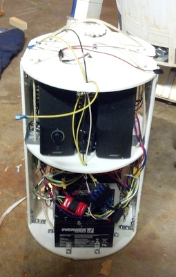 Finished core with batteries mounted and electronics installed |
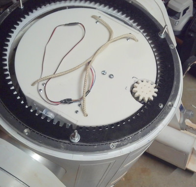 Finished core with dome motor mounted on top installed in R2-JE |
| Pictures here were downloaded from Andrews R2-JE Facebook page. | |
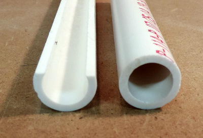 I'm starting with 1/2 inch schedule 40 PVC pipe with an edge cut off. |
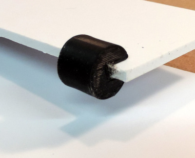 I used my 3D printer to create circular guides that would fit the PVC pipe and mount on the edge of a styrene sheet. |
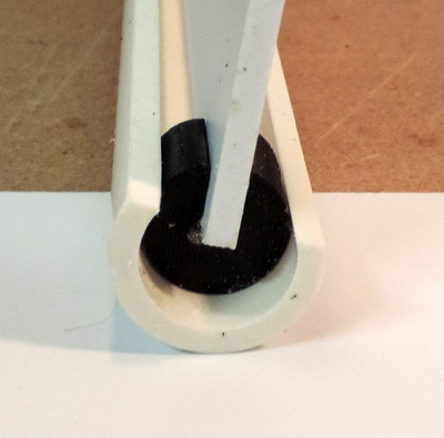 |
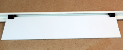 for this 'proof of concept' test I only used guides at the top & bottom of the sheet. In the actual core design the guides will be installed at ring locations on the frame. PVC pipe will be used on each side of the area where the removable back panel will be as well as other locations on the frame. One lesson from the proof of concept: The edge of the guide needs a slight taper to make inserting the core easier! Even though it doesn't look it, it's not possible to 'pop' the guide out of the pvc pipe by pulling on the plastic sheet! |
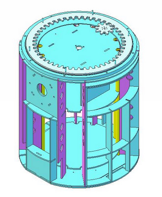 |
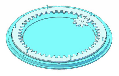
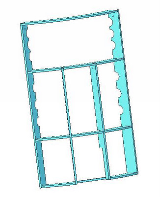
This is the the
full frame, viewed from the rear left side. It includes: The "dome
motivator" - a gear drive mounted on a Rockler Bearing.
The removable core insert that ties the frame together mechanically. It has been replaced by the Tab Core Insert. see R2.CSR.Tab.Core Warning: The balance of the NextGen Frame instructions will show the now obsolete PVC Core Frame The removable rear door frame The removable CS:R Utility Arm Box (new) As a result, this image is a little cluttered with detail. The images will become progressively simpler as I strip away parts. |
 |
The
Dome Motivator is a Pololu gear motor (I understand that there is an
alternate, cheaper, source for the same motor) and hub attached to a
gear drive. There's nothing new in the design of this part. What's not shown, and is a work in progress, is a dome ring design that will accommodate rings of varying sizes and provide a clean mount for the dome itself. Note: the Pololu gear drive motor & the Rockler Bearing are shown for illustration. I do not include mechanical parts in my parts packages. |
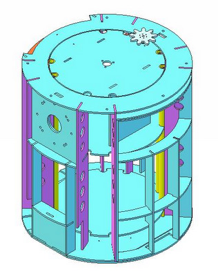 |
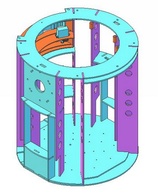
CS:R Frame with
removable Rear Door Frame and removable Core Insert. Features: Frame bottom is a pair of ring panels, ribs only penetrate the top panel (ring1) leaving the bottom panel (ring 0 - the base of the skirt) without holes that need to be filled. Ring 1 has cutouts to accommodate parts that need to be mounted on the bottom edge of the skin (Power Couplings & Octagon Ports) Eight full height ribs (in purple) support the removable core. Four of those have to be trimmed at the bottom to provide clearance for parts mounted on the skin. |
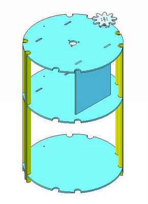 |
This is a
partially filled out version of
the original PCV Removable Core Insert. It has been replaced by the Tab Core Insert. see R2.CSR.Tab.Core Unfinished Items: There are 4 more pieces of conduit on the edges in the obvious places. Note: the Pololu gear drive motor is shown for illustration. I do not include mechanical parts in my parts packages. |
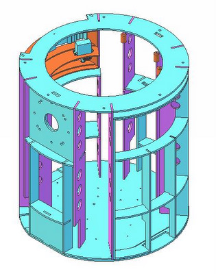 |
CS:R Frame with
removable Rear Door Frame Features: Shown here in orange are the 3D printed pieces that slide inside of the conduits on the insert (called sliders). While the top edge of the slider is chamfered. The top set should also be slightly staggered in height so that the insert only engages one at a time. That should make the insertion process easier. Unfinished Items: additional Sliders will be placed lower on the ribs around the area of the frame rings to couple the frame into the insert in the areas of maximum stress. See the assembly instructions for more details |
 |
CS:R Rear
Door Frame The Rear Panel is actually 3/16" short. The skin will extend below the bottom edge of the Frame and cover the exposed edge of Ring 0 (the skirt base) The Door Frame ribs are only 1/2 the depth of the Frame Ribs in the rest of the frame that was done deliberately to enable wiring to be routed into the back of the Core from the rest of the droid (see below) |
 |
CS:R Frame with
Rear Panel Removed |
| Home |