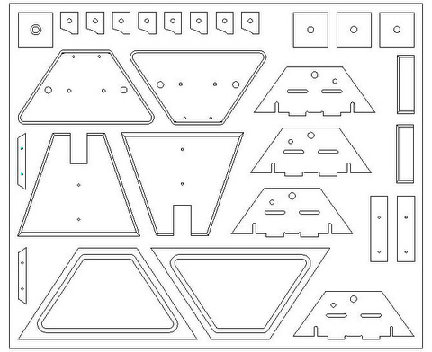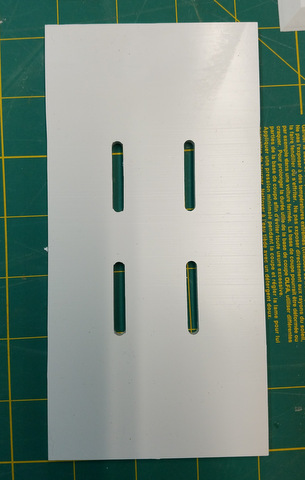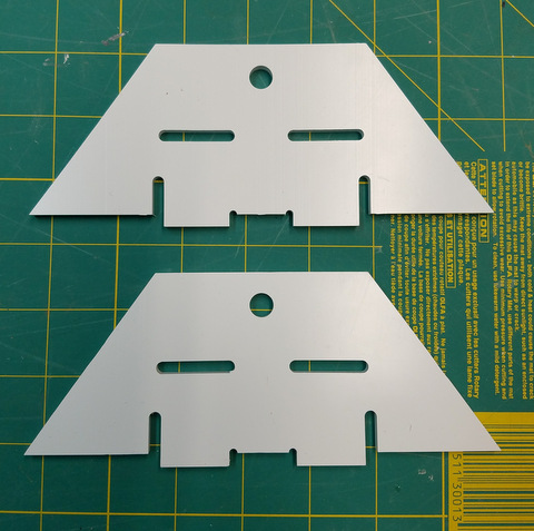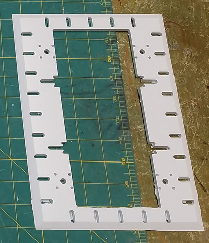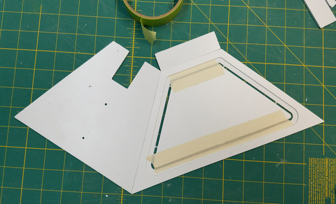
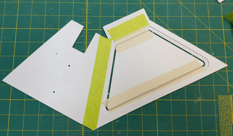
Tape the center section of the side panels
in place to improve the rigidity of the panel |
Place the
panels on a flat surface,
bevels down, and tape the edges. Make
sure the top
and bottom corners line up.
 |
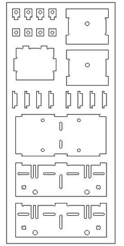
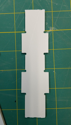
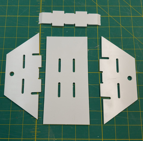
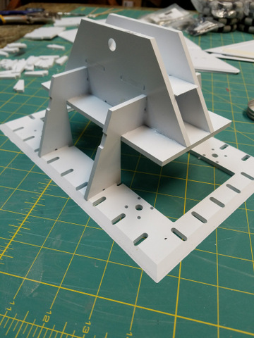
Then
fold the pieces in together to make half of the pyramid shape. Fold the
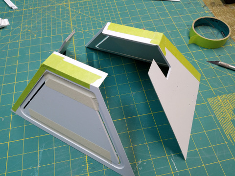
Top Strip down and tape.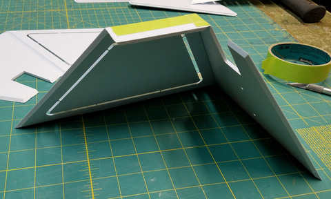 Right: repeat the process
for the other half shell Right: repeat the process
for the other half shell |
|
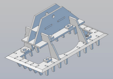
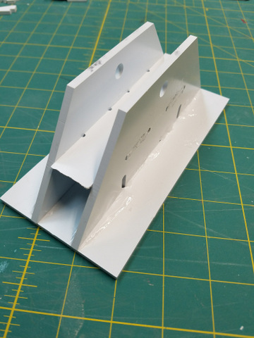
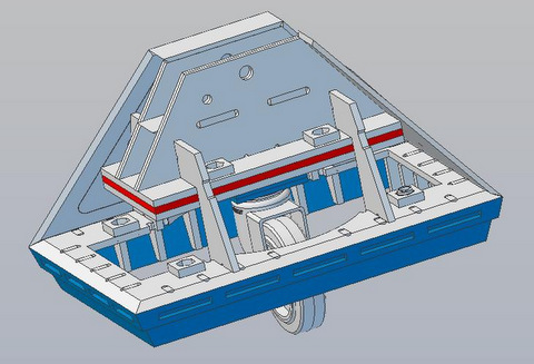
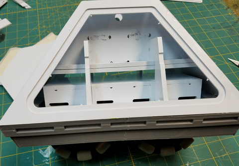
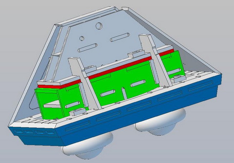
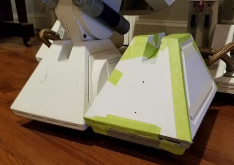
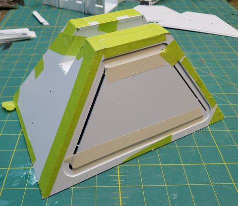
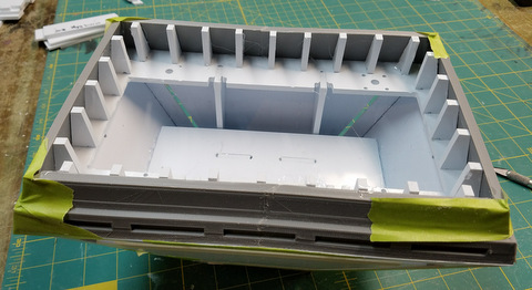
With the panels
taped together, it's time to do a test
fitting to see how the foot shell fits over the structural frame.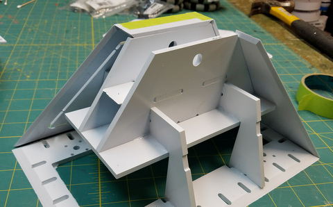
Right: Make adjustments in the structural frame for fit. Tape the two
half shells together around the frame once you are happy with the fit. |
 |
|
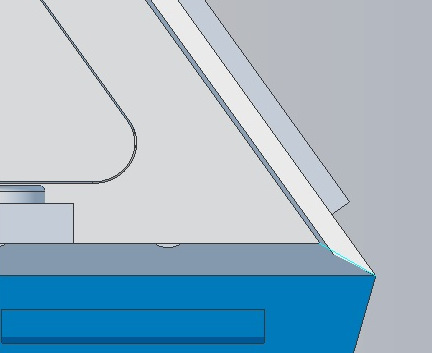
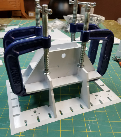
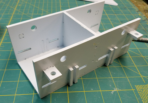
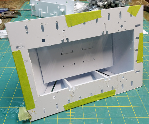
Turn the frame on
it's side and glue the shell to the frame. You won't be able to reach
all the areas that need to be glued yet.
DO NOT GLUE THE CENTER
SECTIONS OF THE SIDE PANELS!
Once the initial glue joints have dried, remove the tape holding the
center sections of the side panels in place. Those openings will give
you access to the rest of the shell's glue joints. Do a second pass
gluing the shell to the frame.
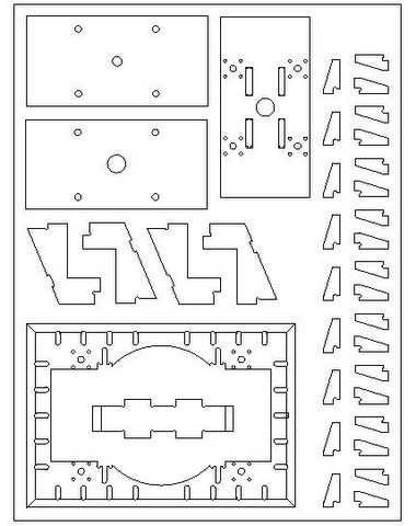
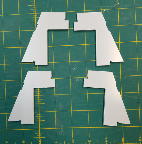
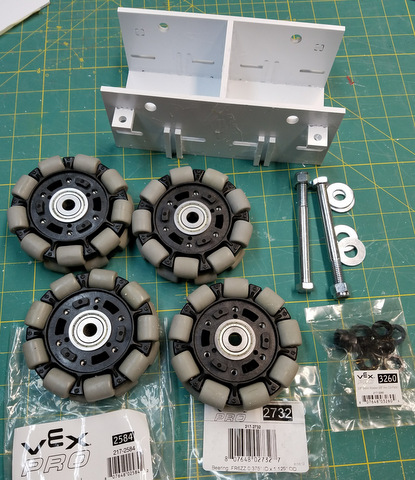
Next, once the glue joints are dry, we
will add the apron braces and
the apron parts to the bottom of the shell
|
|
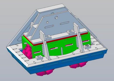
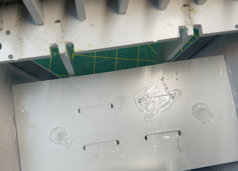
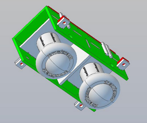
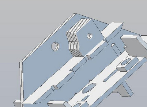
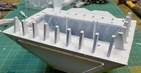
The Apron
Braces are designed to offer more support to the apron pieces than the
previous center foot design. They also provide an anchor to clamp the
apron parts to.
The Bottom Plate is also a solid surface in this design. The previous
design had needed putty to fill the void between the Shell and the
Bottom Plate.
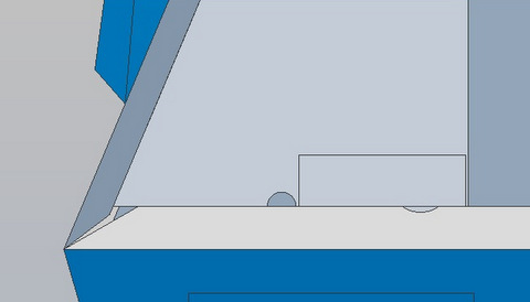
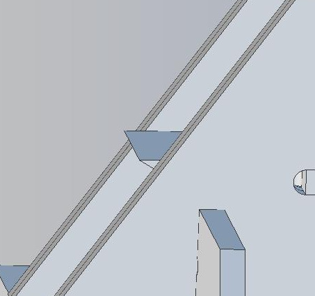
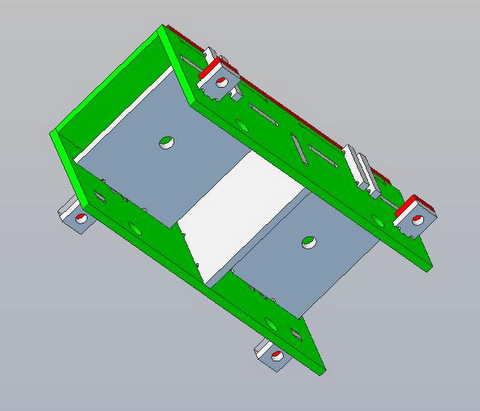
Note: make sure the brace pieces are lined up. The inside edges of the
braces should be vertical. Note the brace marked in the pix is out of
line.
|
|
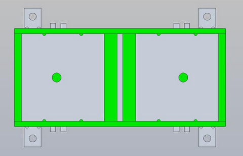
Apply the 3D
printed Apron trim parts to the Bottom Plate.
Note: Apron Braces are now cut shorter than the Apron to eliminate the
need to file them lower so they don't show.
Depending on how your Apron was printed you may want
to reinforce the corners by filling in the corner voids with an epoxy
cement or similar product.
|