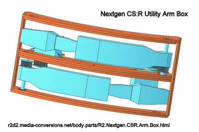
Click on the image for a 3D .pdf version of the original arm box.
Full details of the original on my design/assembly web pages at
r2d2.media-conversions.net/body.parts/R2.Arm.Box
|
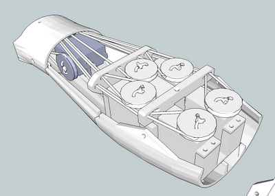
My original Eggcrate Frame was different enough from Dave Everett's
Styrene Droid Design that I had to design my own Arm Box so it would
fit my frame Click on the image for a 3D .pdf version of the original arm box. Full details of the original on my design/assembly web pages at r2d2.media-conversions.net/body.parts/R2.Arm.Box |
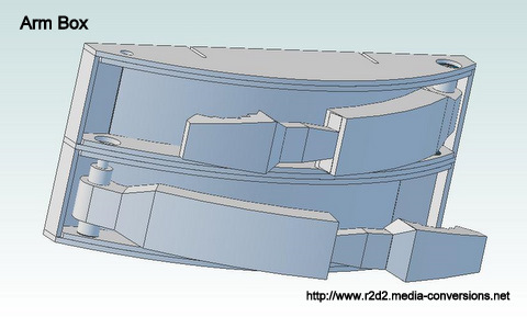
| This design has a few
shortcomings. There
was no way to support the sides of the Box - the only attachment point
was at the bottom. Height had to be adjusted using layers of
plastic as spacers. When I did the design, I assumed that anyone who
would want to make the arms move would use mechanical linkages to
servos mounted behind the box. I wasn't happy with that design because
Jr. Jedi knights like to manhandle anything they can get a hold of on
an R2 and a mechanical linkage would get bent. |
|
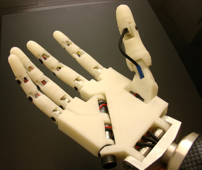 |
While the
printing project for Reed was an interesting exercise. More infomation is at the project's main web site: http://www.inmoov.fr/ The details of the Hand are at: http://www.inmoov.fr/hand-and-forarm/ It also shows up on: http://www.thingiverse.com/thing:17773 |
 |
One of the
things I found useful was the method used to move the fingers of the
hand. The servos for the fingers are located in the wrist. A pulley is fastened to each servo and a pair of kevlar fishing lines is run up to the tips of the fingers. One thought I had was that I could use a similar mechanism to move the utility arms. |
| Home |