The 3D Printed Battery Box

Standard & with Cutout

I originally designed a battery box built using custom heat formed styrene sheet for the semicircular ends of the box. All of the parts were cnc cut for accuracy, overlapping joints were used for strength. For maximum internal volume there were no internal supports inside the box. I actually assembled one box myself and made enough parts for another two. The design was workable, but manufacturing the bent ends was going to be difficult. Then along came 3D printing technology and it solved the problem (but also added some complications of it's own!) You can see the details of the original design here.

Along with the problems of heat bending styrene sheet, I was not happy with the design of the access door. The 4 small screws were going to be a problem and once the screws were out, there was no way to 'grab' the door panel to open it. In addition, I really wanted to be able to make battery boxes that would mate with the foot drive I was designing and that would require cutouts for the motor. 3D printing gave me the opportunity to solve these problems.

This is the 3D Printed Battery Box

The image links to a 3d pdf file, click on it if you want to be able to rotate the image around and examine it from other angles. (Note, the 3d.pdf file opens in a new window. If you have problems with the 3d feature you may have to upgrade to the latest version of Adobe Reader).

After 'activating' the 3d mode by clicking on the display
select a part by left clicking on it (the part will be highlighted)
then right clicking brings up a window.  Follow the sequence
-> part options -> part render mode -> transparent
to make the outer parts transparent and the inner
details visible.


Instead of a door panel on the side of the box, the entire side slides out. It's attached to the end of the box and held on by two flat head screws.

This image, and its associated  3D .pdf file are shown with the door partially opened.
This version of the 3D Printed Battery Box is intended to be used with  my outer foot drive. Because the Scooter motors stick out into the Battery Boxes I've added cutouts to the parts to accommodate the design. In addition I've also added mounting holes that match bolt locations on the foot shell so that the battery box can be securely attached.
As with the previous design, the top and bottom pieces are deliberately oversize to be filed down to match the exact contour. See the Assembly Instructions for the highlights of what you'll have to do by hand. I've put in some panel lines at the top and bottom of the front and rear panels. This was done to hide the joint. If you object to having panel lines where the original R2 did not then let me know since I can make the parts without them.

As I worked on this design It evolved. Here's a small glimpse into the design and problem solving process.
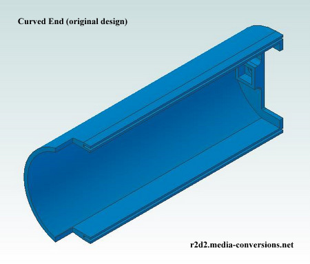
This is actually the second version of the curved end design. The first one utilized a Barrel Nut. However, in order to install the nut there was a separately printed 3D part that held the nut and then that part was glued into the curved end. Converting the design to a square nut meant that the nut trap could be printed  as part of the curved end.
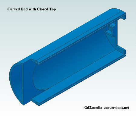
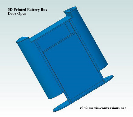
I actually cut parts to go with the original version and got to the point of assembling the prototype when I realized that I was hand fitting a small piece of plastic at the top that should have been printed as part of the design.

I didn't think of doing it originally since it represents what's called a "bridge" in 3D printing terms. However, adding the curved transition makes the "bridge" easy to print reliably.
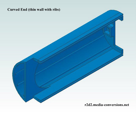
I thought I was done designing curved ends when the one I was working with slipped out of my hands and hit the concrete floor of my workshop. To my surprise it had split along the print layers. Something that I had not experienced with other parts I've printed. This one, however, at over 7 inches in height, is the tallest part that I've printed so far. There were a few changes made so that the parts were more durable. First, I enclosed the printer to raise the ambient the parts are printed in from ~20 deg. C to ~25 deg. C. Second I increased the temperature of the extruder from 230 deg. C to 234 deg. C. This helps the layers stick together better. Finally, although it's counter intuitive, I reduced the wall thickness of the part from .125 in to .1 in while at the same time increasing the internal fill ratio from 20% to 80%. Basically it means the parts are almost solid. Internal ribs were also added to strengthen the parts. They can now survive 3 drops without any damage!

The design drawings are available as both Autocad .dwg files, 3D .step files, and Adobe .pdf files download drawing files with the understanding that the drawings are copyright to Media-Conversions and are not to be used commercially. (That note also appears on each of the drawings).
I've also put together a set of assembly instructions to help you put the box together.
 
Please send me comments, questions, or suggestions on making the design better to me at: fpirz (at) media (dash) conversions (dot) net


Home