The Hex Center Ankle

Some Background
I designed the original "Eggcrate Center Ankle" in 2012. It was built using an Eggcrate frame for the non-structural parts of the ankle.
I incorporated a barrel nut (sometimes called a dowel nut) into the design to anchor the ankle to the frame because I'm not comfortable with the idea of tapping threads into styrene. It wasn't until 2013, when I completed the design of the Center Foot, that I had to deal with attaching the Center Foot to the Center Ankle. The design that I came up with then was a compromise. It consisted of a 3/8 in aluminum spacer tapped to take a pair of 5/16-18 x 1/4 shoulder bolts. The builder had to file a flat on the spacer and install a set screw into the bottom of the Ankle to make sure the spacer wouldn't rotate. There were two aspects to the compromise. The first is called 'galling' (see here for more info ). Galling occurs when Bolt threads seize to the threads of a tapped hole (or a nut). Steel Bolts and Aluminum threads are not a good combination. The other is the nightmare of the insert spinning around in the ankle and no way to get to the set screw to tighten it. In 2018 one of my customers wrote to me about the solution he used when he cut his own Center Ankle parts. Kurt Greenwald substituted a 5/16 in coupling nut that has a hexagonal shape for my threaded spacer. I had searched high & low for off-the-shelf threaded spacers but never encountered coupling nuts! That one change takes care of two problems! It's a steel on steel joint and there's no way it can rotate!
Thank You Kurt!!  

In 2018 I had a different problem, My CNC shop took delivery of some .220 styrene sheets that were really .250 thick. The structural part of the center ankle in 1 in thick. It's original design used 4 pieces of .250 plastic that was readily available in 2012. Sometime around 2015 the styrene wholesalers 'downsized' .250 sheets to .220. The simple solution was to put a .125 sheet of styrene in-between the 4 sheets of .220 (4x.22 + .125 = 1.005). My CNC shop didn't check the sheet thickness and neither did I. Customers contacted me complaining that their ankles would not fit their feet! About 20 of them! I had to ship replacement parts cut from real .220 stock! Other builders have experienced difficulty obtaining .220 styrene to cut their own parts. When I did the re-design to incorporate the Hex Coupling Nut I also converted the design to using .1875 (3/16) thickness styrene which is more widely available.

I've update the drawings here to reflect the changes in the design and also updated the assembly instructions. The original "Eggcrate Center Ankle" web pages are still available here.

pix not yet updated
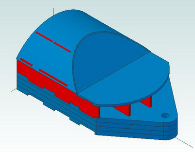
This is the full center ankle (with only the edge skins missing)

The image links to a 3d pdf file, click on it if you want to be able to rotate the image around and examine it from other angles. (Note, the 3d.pdf file opens in a new window. If you have problems with the 3d feature you may have to upgrade to the latest version of Adobe Reader).

After 'activating' the 3d mode by clicking on the display
select a part by left clicking on it (the part will be highlighted)
then right clicking brings up a window.  Follow the sequence
-> part options -> part render mode -> transparent
to make the outer parts transparent and the inner
details visible.

Or you can use the views below which also link to .pdf files.
pix not yet updated
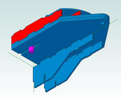
This is a partial view of the center ankle with parts made transparent so you can see the barrel nut.

The image, like the one above, links to a 3d pdf file.


As with any design, there are limitations to what can be reasonably accomplished by CNC machining.  You might have noticed the red lines in the curved part with Skin drawing above. Those are the edges of the ribs 'sticking' through the skin. I had a choice. I could make them the hight of the rings but then you'd only get support on the edge. Instead I made them higher. They will have to be filed down to match the contour of the rings. See the Assembly Instructions for the highlights of what you'll have to do by hand.

The design drawings are available as both Autocad .dwg files and Adobe .pdf files download drawing files (files not yet updated) with the understanding that the drawings are copyright to Media-Conversions and are not to be used commercially. (That note also appears on each of the drawings). I've also put together a set of assembly instructions to help you put the ankles together.
 
Please use the Contact Form to send me comments, questions, or suggestions on making the design better.


Home