Mounting Engraved Skins

I owe the concept of "engraved" single layer skins to Paul Murphy (joymonkey). Just for background, I suggest that  you review the information in Paul's original part run  Forum -> Droid Parts! -> Archived Part Runs -> BC Approved: Single-Layer Milled Styrene Skins he also has mounting instructions in his forum entry. You should also review Dave Everett's Styrene Droid skin files for background even though they are for 2-layer skins. You can find them at Downloads -> 01-Official -> Dave Everett Styrene Files -> 02 - Skins.zip There is good information in all 3 places.

First, a disclaimer or two. The pictures that follow were made using the 1st and 2nd prototype of the Frame and the 1st and 2nd prototype of the skins. The released versions of both the Frame and the Skins are slightly different. The difference is not enough to change the assembly process. I'll also be the first to admit that I'm not an experienced Droid builder. Best example is my opening web page that shows my CS:L Droid. He's very embarassed to be running around mostly naked! The tools and techniques illustrated here are what I used and for the most part what worked for me. You may want to work differently or have seen a build log that illustrates a better way! (If you do, let me know, I'll add a link to it!)

I've broken this into sections for easier navigation
Tools
Frame Preparation
Mounting the Rear Skin
Rear Skin Alignment
Gluing the Rear Door Skin
Completing the Rear Skin
Mounting the Front Skin

Fitting Utility Arms & Fixed Shoulders

Tools

Before we start mounting skins we should talk about tools that will help the process.


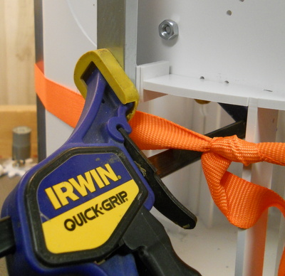
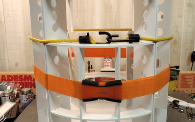
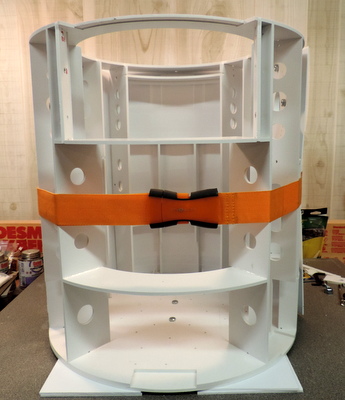
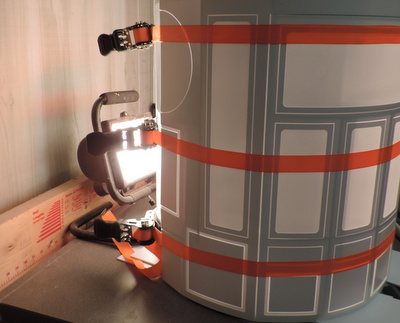
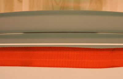
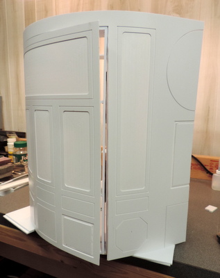
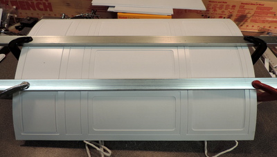
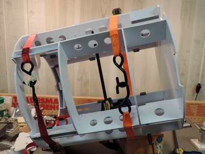
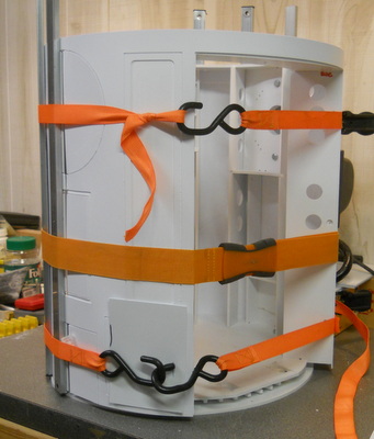
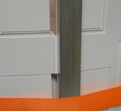
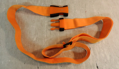
This was originally a luggage strap. I use it in place of a bungee cord to hold the skins in place while fitting the band clamps.
Unless you have a helper you will need something like it.

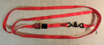
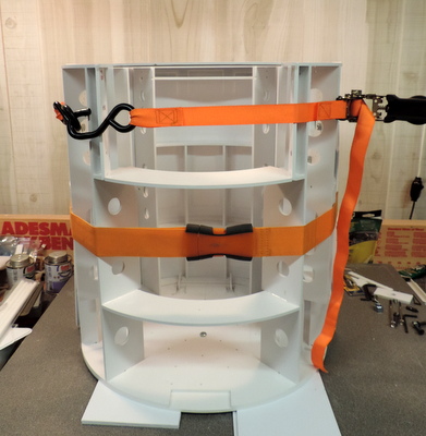
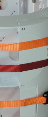
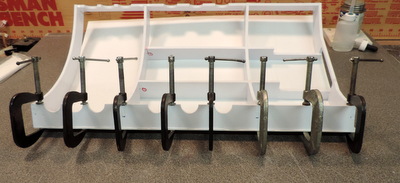
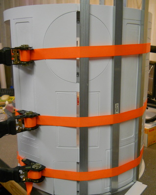
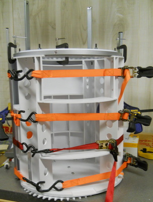
I've allways called these band clamps. However, they are known better as "ratcheting tie downs". If you not familiar with them check out this additional information (it includes places you can buy cheap clamps!)
In the instructions that follow they will be called band clamps.

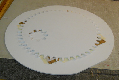
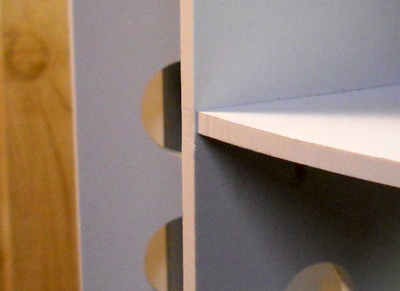
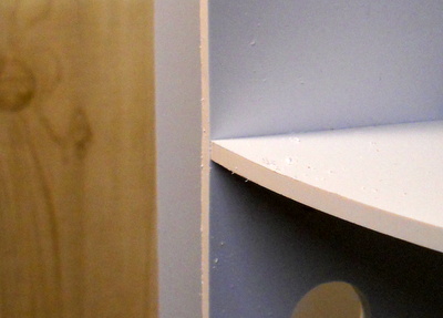
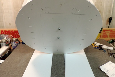
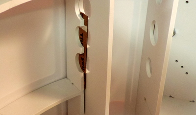
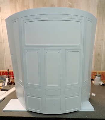
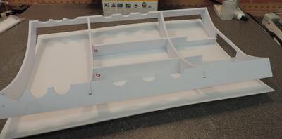
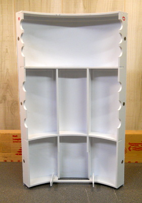
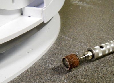
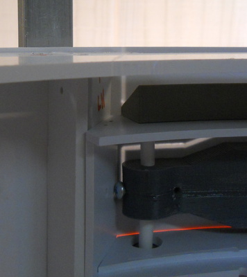
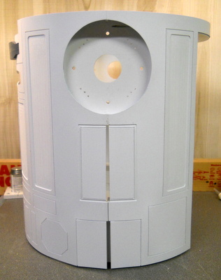
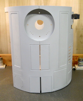
We are going to be working without the Ring0, the bottom ring, attached to the frame. It will make the skin install easier. The frame needs to be raised up so the bottom edges of the skins clear the working surface. You'll need about .25 inch of clearance.

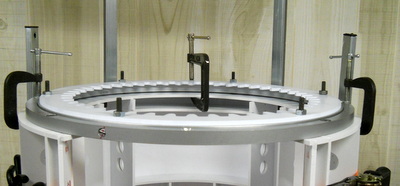
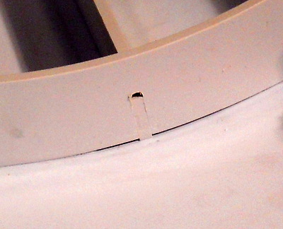
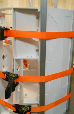
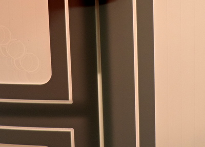
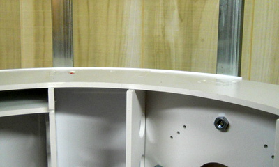
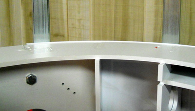
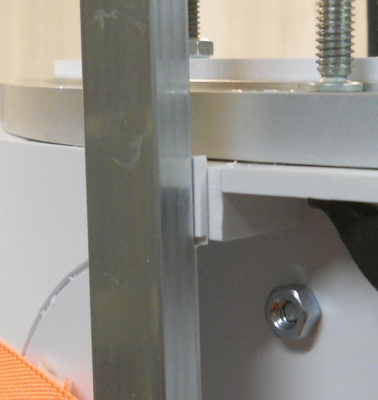
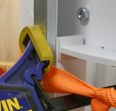
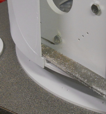
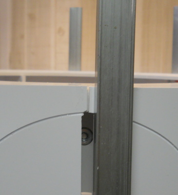
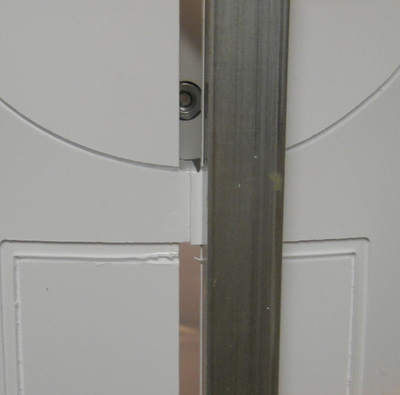
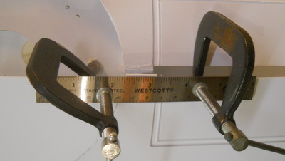
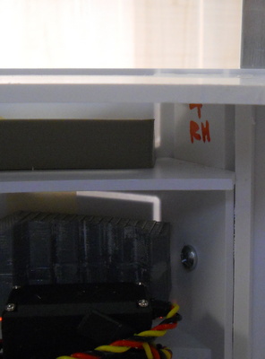
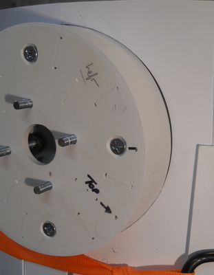
Even though the frame is made of .1875 (3/16) styrene you'll find the rings are easy to deflect slightly up and down. To hold the top of the frame flat it's a good idea to clamp your Rockler bearing in place.

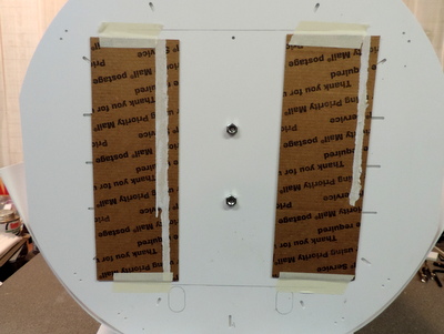
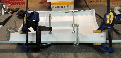
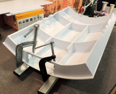
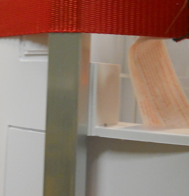
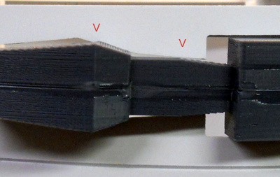
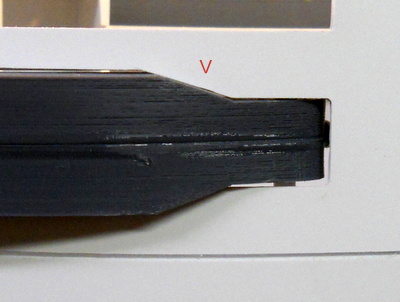
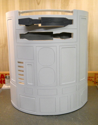
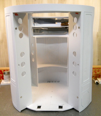
Pauls instructions called for pieces of angle iron to keep from distorting the frame. I used pieces of square metal tubing in whatever sizes they happened to be when I grabbed them. BAD IDEA.

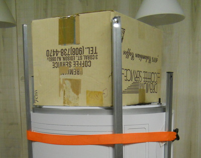
 When I went to turn the frame over in order to work on the bottom I found I needed a very big spacer in order to reach past the oversize pieces.

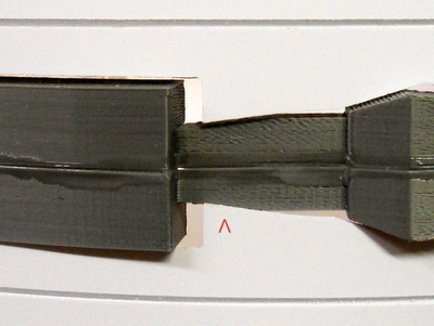
I've since cut those pieces all to 24 inches!

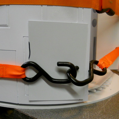
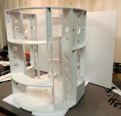
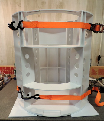
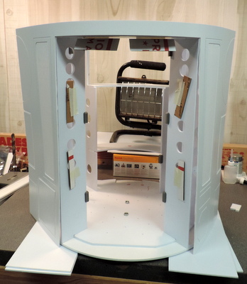
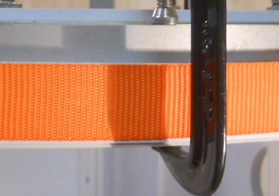
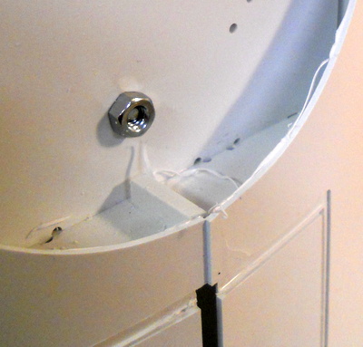
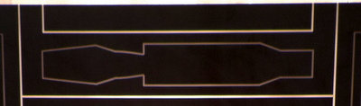
If your band clamps have big iron hooks you'll want to put something between them and the frame to prevent scratching your skins

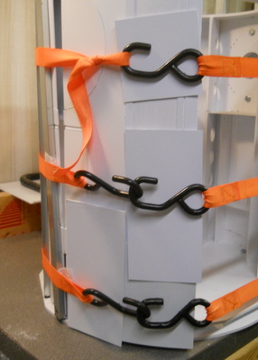
You'll also want to be sure the hooks don't get caught on the edge of a rib as you are tightening the clamps
Finally, you'll need some clamps. You most likely already have an assortment of C-Clamps. But the skin mounting process is a special challenge! You'll want some deep throated clamps that can be tigthened with one hand. The Irwin clamp shown to the Right is just one example.

Frame Preparation
Before trying to mount your skins double check your frame for ribs and rings that are not precisely aligned. The SciGrip (Weldon) #3 cement used to bond the skins to the frame requires a contact fit
between the surfaces being glued. File the edges so that the high spot is removed.

here is an example of a rib/ring not precisely aligned

this is the result of filing it down
Left: here is what happens when you don't check the alignment
that small gap will prevent the skin from fusing to the ring

If you find cases like this during your build you can go back with a tube of SciGrip #16 which will fill the void but is not as good a joint using the #3

Mounting the Rear Skin
We start with the rear skin! This allows us to remove the rear door when we are done with the skin and that gives us access to the front of the Droid while we are mounting the front skins.

Start by making sure your bungee cord or strap will reach around your Droid. I'm working alone so there's no opportunity to stop and adjust the length of a strap
.

For the moment Ring0/skirt bottom is bolted to the bottom of the Droid. I'm using a couple of pieces of scrap to raise the bottom above the bolts.

Since the skins are oversize top & bottom by .0625 I'll also need to have the frame above the bottom edge of the skins.

with everything ready to go, put the rear skin behind the driod

circle the rear skin with your strap and pull it tight. you've started the mounting process!

with the skins held in place start putting band clamps around your Droid.

start out with one top & bottom, you only need it tight enough to keep the bands from slipping

you'll need bars of some kind to put extra pressure on the skins at both the ends and over rib locations to get good contact with the ribs.Once the bars are in place add a third (and possibly a 4th) band clamp.

Rear Skin Alignment
Now that you've got the rear skin held securely down, it's time to start the alignment process. This is my first skin, so I'm being cautious. If I didn't have a rear door I would just rely on the position of the skins edges on the attachment points. To be doubly sure I'm also verifying the skin position at the door edges.

One of the things that helps me determine if the skins were aligned properly was a strong back light.
Right: you can see the rear door and frame ribs on the panel line

Left: the shadow changes as you rotate the frame in front of the light. position the frame so that the light is pointing directly at the joint between frame and door.

Above: To confirm skin alignment I inserted a thin piece of cardboard between the door rib and the frame rib.

now you can see the location of the cardboard by its shadow.

you can use the same method to check the top door frame ring. you might have to raise the light up higher to do this.

Left: Also check the skin alignment at the attachment blocks.
Above: I've never been able to get the applicator bottle to work well for me so I'm using an eyedropper to dispense the Weldon #3
The strategy I'm using to start the gluing process is to get the skin glued to the rings and ribs at the middle of the door.
I've also glued the skin at the top edge of ring4 and along the rib that's between the shoulder and the door frame.
You want to be sure you don't glue the door to the frame, or the bottom two rings to each other.

The skin should extend about 1/16 of an inch above the top of the frame. That's deliberate.

It can be filed down after the gluing process is complete.

To hold the top of the frame flat it's a good idea to clamp your Rockler bearing in place. You don't have to bolt it, clamps will work fine.

Once the glue is dry and you can take off the band clamps. As you can see there are parts of the skin that are not glued (yet)

Cut the panel line between the door and the frame. I used an X-acto #11 blade to make the cut.

Frame with door removed. Note the cardboard spacers.

Gluing the Rear Door Skin
With the Rear Door removed from the frame we can finish gluing the skin without fear of gluing the door to the frame.

Here's the door with skin partially attached. That attachment gives us the alignment with the frame.

You can use individual C clamps to hold the edge down.

Or put a metal bar between the clamps and the door frame. This is probably a better choice since the skin is pressed against the frame along the full length of the frame. However, you'll need clamps with a bigger throat size.

Above Right & Above:
Repeat the gluing process along the door center ribs. Here you will have to use the metal bars since reaching the middle of the door is all but impossible. Note that the skin extends beyond the bottom of the door frame. That was deliberate. Ring 0 supports the bottom of the door. The extended skin covers the joint.

Right: Finished Door with Skin attached
Left: Inside of the rear door frame.
This is the second prototype frame
it has the magnets and the door keys.

Completing the Rear Skin Mounting
If you have enough clamps you can do this part of the gluing process at the same time as you are working on the door skins above. It takes a bit of bench space, or an alternate place to put the door while the glue dries. I don't recommend it unless you are in a real hurry or an experienced builder.

put the band clamps back on the frame, use bars to put pressure on both ends of the skins and the rib in the middle.

again, pay attention to the alignment at the skin attachment blocks

you may find that you need extra pressure at the attachment points to get a good glue bond

Above and Right: Check the partial ring that forms the top of the door opening. It can sag down. If it is, clamp it so that it's aligned with the skin and then glue it in place when you glue the other joints.

glue all of the remaining joints, or at least as many as you can reach.
carefully laying the frame on it's side, you can get an assist from gravity to get the #3 to flow to places you can't reach.

finished rear skin with door in place.

side views of the rear skin

the skin attachment blocks are cut a little tight to the fixed shoulders

you can file them before you put the skins on

Right: Or, if you remove the circular filler in the skin's shoulder you can use a dremel to improve the clearance. note: the sanding drum has been slid forward  so you can reach all the way to the surface

Mounting the Front Skin
The process for mounting the Front Skin is very similar to the one used for the rear skins. It's slightly more complicated by the alignment of the arm box.

Put the Front skins in place using the belt (or a bungee cord)

then add the metal bars and band clamps

the three skin attachment points are your alignment points

Left & Above: If you find that the front skin is overlapping the rear and needs to be trimmed clamp a steel ruler in place to act as a guide. Use a sharp knife and score and snap the excess skin.

Left & Above:
Use the shop light again to check the alignment of the front skins

Above & Right
verify that the Power Coupling and the Octagon port cutouts line up with the notches in Ring1

Install the arm box and check the alignment of the cutout for the LDP with the edges of the lower LDP

The error  is about 1/2 of the panel line, or 1/32 of an inch.
Not enough to worry about.

Fitting Utility Arms & Fixed Shoulders
While the Utility Arms align with the skin opening and fit correctly it's impossible to extend the arms thru the skins without having them rub on the skins. In the production version of the skins I've enlarged the skin openings for the Utility Arms by .0625. It will help, but not completely eliminate the problem. For a detailed discussion of the problem, and a suggestion for a fix, see the forum posting: A&A Skins and Utility Arms

Above & Right: I modified the Utility Arm cutout on the upper arm in order to 'improve" the fit by changing the angle of the skins slightly
Left: Without changing the cutout on the lower arms it's almost impossible the get the arm to pass thru the opening.

These were second prototype skins. For the first production run I've increased the size of the Utility Arm openings (see below). It's a small amount. The Utility Arm openings now extend beyond the LDP cutout by the width of the line (.0625)
The Utility arms were not the only tight fitting component.

The opening for the Fixed Shoulder also needed to be expanded.
Like the utility arms, the opening was expanded by .0625 for the first production run.

Congratulations You've finished mounting the Skins on your Droid!

Finished Left

Finished Front

Finished Right

Finished Rear with Door

Finished by Richard C!

Finished Rear without Door

Initial Release 02/14/16


Home